Friday, January 28, 2011

Frame making

This is going back a bit in time, in the days of film cameras, dark hair and only monofocal glasses..time may have taken its toll so the descriptions of how it happened may need a bit of recall and editing later on.  Idealy you would start with full project funding, a large shed ready for the hull, the location has to be where noise won't disturb residents either in an industrial zone (ideal) or  in the country (not too far from industrial zone). The climates important - below about 27 deg C, above this and the heats too much when wearing overalls for welding. Easier to see this in retrospect, of course overall i did none of the above ideal things.

The process began with the plans, recommended book reading, a fair bit of study. I'm not a trady, have a science background, but have sailed and repaired a few small boats over the years. I'd never built any boat before, let alone a large steel one..maybe "the little men in big white coats (are coming to take you away, Ha- Ha"..on old song goes) should have been called in at this stage.! But they didnt come so i completed a TAFE welding course, part-time in the evenings. A few construction laboring jobs in the formative years also helped with the needed skill sets.

My wylo began underneath a high-set share rental house in a city of 110,000 souls. An old 1970 XY Falcon station wagon was the workhorse. A 4" angle grinder, 180amp arc welding gear and 2nd hand oxy acetylene cutting gear were bought along with mild steel stock - flat bar and a few sheets of 3mm. A straight edge, tape measure, engineers chalk, paint marker pens and large square were some other starting tools. I used 3.2mm welding rods on the 6mm thick flat bar. A welding/oxy cutting work bench was a good first project to practise my budding oxy-cutting and welding skills on.

Frame lofting

A sheet of 3mm steel used as a lofting surface (on a nice flat concrete floor) A steel scribe was used to mark the frames shape up on the steel sheet. First mark was the centerline, offset tables provided the measurements to mark out the chines and gunwales etc (frame corner points) on the sheet. A template of chines helped scribe the correct chine shapes then theses were connected by scribed lines to make the frame outline. The deck beam camber offset was marked and a flexible wooden batten used to mark a faired deck camber. The smallest frame - Frame 1 for the bow seemed like the logical one to do first.

2" x 1/4" flat bar segments were cut and fitted, joins to be welded were beveled to allow for complete penetration of weld. The first stage was to tack the pieces of the forefoot together. Carefull welding pattern (wish i could remember it) using short welds, then waiting for weld cooling shrinkage to see where the frame aligned on the lofted sheets scribe marks.When the frame was welded it was turned over, any slag from the first phase cut out with the grinder, then the other side welded. The small runs help reduce any distortion of the frame. Its pretty hard to rebend a flat bar on edge if its out, i used weld and quench method. A bead of weld is run down one side and is suddenly quenched with water..this pulls the steel the way you want it to go.

Frame 1 - ready for deck beam bending. The house mates black cat took great interest in the project.

Below is the frame bending device in the process of edge bending the deck beam. Later i discovered its better to cut the stringer notches prior to bending, so modified the bending frame to hold deck beams on edge and hit the stringer notch with a steel mallet, it bent easily at the stringer notch.


Corner gussets were welded in at the frame/deck beam join and at the lower join. This gives it greater strength.  The welds were ground down afterwards.
 Frame 1 completed!

well nearly, it was later laid back on the lofting platen and the hull center line angle iron tacked on (30x30mm section, for eventual frame set up)

One by one frames emerged from the basement, here is frame 5 (amidships)

The cabin end frames...with centre-line angle irons attached.

More frames come out to grace the exterior.

Black cat was always curious whenever something was going on.  Limber (drainage) holes are cut into keel frames at this stage.

The stem and forefoot longitudinal frame is made of 40x10mm flat bar. Hitting floating logs or ice floes shouldnt be a problem, and might even survive a submerged sea container,  but better take it easy around the marina.. (NB: The bender device in background has now gained vertical arms with slots for deck beam bending )

Eventually the day came when a highset suburban house on 700m2 was too small,  so good friends helped load everything onto a hire trailer.

..and unloaded it at the big shed on a 25 acre block out of town. This was potentially a great wyloyard site.. 

Thursday, January 20, 2011

Engine room

There's not too much in my wylos engine room as yet. It has a stern tube, keel cooler inlet and out let pipes fitted for use with a diesel power plant. A tank in the port quarter is about half way there.

Aft peak below lazarette hatch.  The stern tube is lower right. The keel cooler tubes are middle left side of photo.
Aft Peak below the cockpit.
The aft peak - the plan is to have a quarter berth to starboard (right side of photo) and stowage to port (left side of photo). If a diesel is fitted then the exhaust system need to go in through there to the transom.

There are a few options that i've been looking into and weighing up, so far diesel seems to come out ahead but electric is getting better as time goes on..
  1. Marinised diesel inboard (keel cooled)
  2. Marine diesel with heat exchanger cooling
  3. Direct seawater cooled inboard
  4. Electric inboard 
  5. Hybrid diesel-electric inboard 
  6. Outboard - external frame or in well.
  7. Engine-less
  8. Marinised Petrol inboard
1: Marinised Diesel with keel cooling

Currently, a diesel of around 25 -30 Horsepower seems about right. It should be enough power to motor into galeforce onshore breezes, valuable insurance in a windswept anchorage on a lee shore. I'm currently planning to fit an engine under the companion way hatch, this is the normal installation position for wylo2s. In this position the engine box doubles as a platform to stand on and wedge your body against the companionway coaming for a safe viewpoint when on watch or using navigational equipment.

The engine box is also located so that it acts as a nice seat in the galley, a handy thing at sea.

As mentioned earlier the system is keel cooled. Advantages of the system
  1. Automotive engines can be marinised and installed, this leads to cost savings compared with purely marine engines.
  2. No through hull fittings which means fewer underwater holes in the hull, which have potential to let the sea in rather rapidly (the dry exhaust outlet is high above the waterline). Less worry when all the crews ashore.
  3. For river motoring - No saltwater intake to get clogged by weeds (which can lead to possible engine overheating)
  4. Saltwater shouldn't get into the engine via the plumbing.(exhaust back-siphoning..?)
  5. No exhaust seacock hiding in the lazarette to remember to open/close. Wylo2 had a (rubber or cork) bung  in the dry exhaust outlet about 10" below the transom bulwark top.  The bung is attached to the yacht by a thin line and is opened/closed by hand from the aft deck.
  6. An optional water jacket around the dry exhaust pipe can be fabricated and should cool things down before the pipe reaches the transom.  The exhaust jacket plumbing is connected to the keel coolers to dissipate the heat underwater. Heat proof lagging is usually wrapped around the dry exhaust pipe if no water jacket is built.
  7. The keel coolers are 6" wide plates (3mm thick) welded in the join between the hull bottom and long keel side ( the garboards) to form 2 triangular sectioned ducts. The engines hot water outlet and cooled water inlet (return) pipes are welded to the keel coolers aft ends (below the cockpit). A water cross over pipe joins the 2 keel coolers at the forward end of the keel above the ballast box lid.
Along with my wylo plans Nick also sent me an interesting article he wrote for a Seaspray magazine about how he marinised wylo2s ex car engine.  Nick made a header tank which is fitted above engine level. The system is unpressurised so any bubbles that may develop in the coolant circuit can escape via the header tank.

Duet's engine


2: Marine diesel with heat-exchanger cooling

This is the most common way to go most yachts have this. The diesel operates with a heat exchanger - passing fresh engine water through to be cooled by salt water being pumped through the heat exchanger. Some salt water goes into the exhaust pipe and muffler  or standpipe and the exhaust pipe then exits just below the waterline aft to increase silencing. There is usually a high part in the exhaust system and a seacock in the exhaust system to prevent back-siphoning of salt water into the engine which ruins it. You must remember to turn the seacock open/close at the right time when starting or stopping. The other problem is the salt water intake can get clogged with weed etc which can cause overheating and engine seizure in extreme cases.

3: Direct salt water cooling

Direct salt water cooling is simpler but needs a massive engine block with good regularly maintained internal anodes. Lack of maintenance could lead to engine block corroding out early.

4: Midship engine mounting alternative. Some wylo's have their engines mounted amidships in the maincabin. The engine box can be a kitchen bench or the main saloon table. Notable examples are "Ironbark" and "Penardun" (formerly "Otama Song"). They need long driveshafts with extra bearings and a unviversal joint usually. The advantages are more room aft around the galley and the biggest "engine room" ever once the cover box is removed, which makes accesibility around it far better. Weight is more centralised and lower. Disadvantage is the saloon looses some space. 

5: Electric  inboard 

Electric drives are modern alternative auxillary engine systems. Some of the many advantages are they're very clean (no oil, grease or fuel spills and smell), simple and  quiet. There is high torque at low prop revolutions (good for close quarter manoeuvring),  no warm up required, no through hull fittings (with potential for sinking a boat). The motor is small, has no gearbox, lightweight, maintenance is minimal and installation straight-forward.. Battery banks provide the power - Either deep cycle lead acid or lithium ion. A controller unit sits between batteries and motor. Recharging is from internal combustion engine (ICE) generators (hybrid system) , solar panels, wind generator and also propeller-regeneration when sailing is an option.

Compared with diesel the motoring cruising speed of electric drive is generally slower about 3-4 knots for an economical power draw, with short burst of near hull speed. Typical  range under battery power is from 20-30 nm. Diesels can easily power up to hull speed say 5-6 knots and range is many times that of a typical battery bank powered electric drive.

Installation costs still seem to be 2-3x more than traditional ICE engines..this is a major deterrent.

There is still a great deal of debate going on about its suitability for a heavy live-aboard monohull bluewater cruiser such as a wylo2. Here, the forum consensus still seems to lay with diesel. Maybe it's "stay with the devil you know" and economics of it. "Range anxiety" is also a major factor.

The balance in favor of electric may change in future as fuel prices keep increasing and  green technologies improve and become cheaper per Watt. Already the cost of solar panels has fallen dramatically per watt over the last decade making these a must have on any cruising yacht anyway. The next phase is for batteries to do the same.  It's starting to happen in the electric auto-mobile industry in the US. Greenhouse emission targets/ energy independence being the driver for the change away from fossil fuels in some countries. (Not so in the land down-under yet - a staunchly fossil fuelled economy)

An electric drive such as the Thoosa are designed for yachts. There are also other companies where it is gaining popularity. Electric yacht in the US and Electric boat motors Australia have yacht motor products.

Elco motor yachts, established in 1893, make a nice looking "traditional" looking range of electric inboards with plug and play fittings. Checking the utube videos, Their motors seem to run very cool, very smooth and very quietly. They also setup serial hybrid systems (generators to all electric) Private and commercial vessels including a vintage NY tugboat are operating with these (upto 100hp) Great article about this company and the not distant future potential of battery developments - "100 years of electric boat development". Once set up the operating costs should be allot less than internal combustion power.  It's not far short of 10k USD for an EP2000 (20hp suits a wylo) with accessories (and no batteries) similar to a Thoosa.


All-electric systems seem to be more favourable for weekend, racing monohulls or multihulls.   Only a small motoring range is needed. Moored boats can have enough time to recharge using a  solar panels. Berthed boats can plug in for recharge.

Trimarans - Current Sunshine  is a trimaran which gets around Australian waters totally on sail and a  Torqueedo electric outboard motor powered by Li-ion batteries and plenty of solar panels etc. Multi-hulls have allot of deck area for solar panel recharging systems. Their easily driven hulls don't need much horsepower to move at a respectable speed either, unless there is a strong headwind. In catamarans twin electric motors would be needed which doubles the cost for the motor but only one ICE generator would be required to recharge.

Some cruisers have re-fitted electric motors and happy reports are coming in, some of these have backup generators to gain the more range when it's required. A very good read is Biankas blog, Capt Mike fitted a Thoosa 9000 in a Nonsuch 30. Four MK8A4D AGM 198 AH batteries were fitted on a platform where the old ICE engine used to be, cost estimate was about 11-12k USD. In addition a Honda i2000 petrol gen set and a solar bimini generate electricity. Capt Mike has no intention of going back to the old ICE age.  The blog details step by step how to convert from ICE to electric drive. Photos of before and after, or the complexity vs simplicity help to lift the veil on the topic. Later posts tell how the system is working - performing well, Bianka's Thoosa has been operating for about 6 years old  now.


Diesel gensets can be installed anywhere that's convenient or unobtrusive down below for offshore voyaging yachts..  Small petrol gensets on deck can also work ok for coastal sailing. A generator aboard also means power tool use almost anywhere.

Electric engined yachty's mindsets must be somewhere between the engine-less and the fully powered up but probably closer to the englineless end of the scale. Be prepared to sail as much as possible, go slower, have an efficient suit of sails, wait for the turn of the favourable tide. "Electro-sailing" (motor sailing) is used allot. The electric throttle can be set so that when the wind picks up the boats sails and even regenerates, when the wind eases off the electric motor kicks a little to keep the hull speed up. Even a small input of 100watts when sailing can add about a knot to boatspeed the prop is not adding drag and is pushing forward slightly. Also in slow speed manoeuvring the electric has far more slow speed power and control. A big diesel runs at a minimum of 5-10 HP idling, the electric can go at small fractions of a horsepower when needed. Electro Marines James Lambden demonstrates and explains the advantages of an electro-powered sailing yacht.

The big advantage in long distance cruising without a tight schedule is little or no fossil fuel needed or consumed. It may be good when going to very remote places where  fuel is very expensive and/or very hard to find or even buy.(ref. Iron Bark blog ) Electric drive would probably reduce the amount of times refuelling port is required which could improve remote route planning. How many times have yacht voyages have been held up or diverted because of some difficult to get engine part breaking down?

The electric auxiliary has reached the ranks of wylos at last! The first Thoosa 9000 powered wylo in the world was launched recently (2015) in Canada.

Was surfing the used yachts pages awhile back, one yacht in Cairns (and a DIY genius?)  retro-fitted an inexpensive old forklift motor to a cruising yacht for some auxiliary power.

A few years ago, with electric boat propulsion in the back of my mind, I wanted to test out something - anything with an electric power plant. I was living in Bangkok so bought a brand new electric-scooter called an "e-zip 450" from LA Bicycle Thailand for about $400 AUD.  It had a 20km range, did  up to 20km/hr and was recharged overnight at home.  In a hot-humid environment, it kept the sweat-levels down when riding to the local market or car-park (no car park space at the house).  It was just right for these short-distance low-speed trips through the narrow Soi.(side streets and laneways). The ezip has a notched belt drive straight from the 450 watt motor to the back wheel with no gears. (see the similarities with the Thoosa motors drive)  The flat lead acid battery is fitted  under the riding board which kept the centre of gravity low.  The cleanliness, quietness and low-maintenance were great attributes of this scooter.


Batteries - Deep cycle Lead acid batteries are the traditional and cheapest to buy ones. They are very heavy and bulky for the power storage, the life is 3-5 years and they must not be discharged below 50% anytime if a long life is to be had. The next step up in leadacid is AGM absorbed glass matt.

LithiumFePo4 batteries - these store ?twice as much power to weight, cost 5-6 times as much but last many times longer than lead acid. They can also be discharged allot more (90%) without damage.  Better way to go if the upfront cost can be handled. The next few years could see a price drop...

Future battery type improvements (plus fuel price hikes and economic factors) could really swing the pendulum towards electric.

6: Hybrid diesel-electric

Hence the development of true hybrid electric marine drives such as the  hybrid marine electric propulsion unit which was intitially developed for canal boats in the UK and Europe which need a fair days run. They also get allot of spare power for all the electrical home comforts. These hybrid drives are being developed for marine use too, a 12 HP hybrid drive is aboard 32 foot wylo Maud and larger hybrids are in 35 foot full keel gaffers built by Voyaging yachts of Cowes, UK.

Hybrids overcome the low-range and low-power problems of the all-electric drive with performance similar to any combustion engine with all the advantages of electric too, such as gliding almost silently along at times. The operating mindset can be as for ICE engines, plenty of power available. But it's probably the most expensive engine option too.

7: Petrol Outboard (in a well)

The biggest advantage of outboards is they can be easily removed for shore maintenance, no crawling around in the engine room only to forget that part needed and have to go ashore. But for a 7 tonne yacht the horsepower would have to be at least 25-35 HP with a sail drive prop .  That's a large outboard to handle so the only safe- seaworthy place would be in an inboard well. I've never seen one on a yacht the size and weight of a wylo. 

They might best suit for harbour, estuary or river use over short-medium distances, with minimal rough open water use. Perhaps a cheaper option somewhere between electric and engineless (yuloh oar sculling)

Outboards fuel consumption and range isn't very good either. Petrol must be stored in well ventilated spaces which self drain overboard.  There are diesel outboards but these are costly.

An inboard outboard well which allows the  propeller to be further inboard and deeper below the hull  It is more seaworthy than a transom mounted outboard but at the expense of some lost space. I had this arrangement on a 24 foot fibreglass sloop with a 6 hp petrol longshaft and it worked very well, especially in rough seas. It actually saved the boat when the rudder was lost and a narrow dangerous harbour entrance had to be passed in rough weather, I could steer the boat with the outboard from inside the cockpit.  The motor was light enough to lift straight up into the cockpit, then stow, it could not be tilted up as the well hole was too small. Some small yachts in the 20-30 foot range have tilt-up outboard well designs (eg SV "Atom"), they tend to be fiberglass or WEST plywood boats. Inboard outboard wells suit classic craft, double enders, net fishing boats. It protects the motor from external damage too.

External outboard bracket mounting (as on trailer sailers) would mean the use is limited to sheltered waters like harbours etc.

 However to scale up a seaworthy and safe outboard well or external bracket to a wylos size would take much engineering ingenuity and then it would be an experimental prototype.


8: Englineless

It's clean, simple and saves internal space and cost. The downside is drifting away from the destination or onto something unforgiving like a reef, wharf or another boat. Allot of skill is required eg Kevin Boothby - How to sail Oceans u-tube channel has a playlist on enginless/yuloh seamanship. Kevin points out this is definitely not for everyone, but for those inclined with the time and skills, it can be done fairly safely. Allot of thought, planning and knowledge has to go into every time the boat is moved. Kevin's video's and teachings on engineless sailing are the most comprehensive i've found online so far.

A select group of experienced long distance sailors have sailed engineless successfully. eg Lin and Larry Pardey  and  Zeebeedee, NZ.  Cindy Wallach of sailing Magazine's article on engineless cruising sailors is interesting.

Wylo 35 "Io" employs a long Yuloh sculling oar over the transom to move about in windless flat conditions.   A crew member in the dinghy with outboard could also be used to tow a wylo in similar conditions. When the breeze gets up sailing is the only option. Very good ground tackle and seamanship skills are required.

A very strong anchoring bollard or two on the fore-deck might be needed for being towed.

Everyone has a different take on this subject, for me engine-less is good in small enough boats that can be moved by oars. Such as my Fatty Knees 8 dinghy, it's a great feeling to move about only on wind and oar only. However, i can't sail too far and must stay within "rowing range" of port.  Must be careful about wind/tide and trip planning, there are limitations to a trip. I haven't tried to set up sculling or rowing capability on my 18 foot sloop, moving the 800 kg boat might need some hefty sized oars/yuloh set up (11'6" long, Chesapeake light craft oar calculator)  so the outboard is crucial to any successful trip at present.

In North Queensland coral reef waters the tides and currents can be pretty strong at times (with 15-25 knot trade-winds on top of that).  I like to sail solo, and get to port on time (for work and family commitments), for my sailing area and life-schedule an engine is a must.


9: Petrol inboard

WyloIIs petrol engine has seen good service for decades without mishap. It came out of a van and Nick marinised it from the gearbox up, certainly an economical way to go but very good mechanical skills are required. A good nose, constant careful vigilance and no smoking. Bilge blowers and a vapor detector would further reduce the risk of petrol vapour (heavier than air so could collect in the bilges).

Fires at sea are a deadly business so for safety's sake there probably wont' be a petrol inboard engine aboard.


Saturday, January 15, 2011

Hull and decks

Up forward theres alot of flush deck space. The bulwarks have rounded 3/4" water pipe tops and the deck toe rails are 2" flat bar. The deck is 3mm steel plate. Photo below shows red oxide construction primer.


The hull was built on a North-South axis. I read or heard somewhere that the earths magnetic field gets set into the hull during welding and N-S build orientation would later make the compass anti-deviation easier to set up later.
I made tempoary construction hatches from old house hardwood and sheet metal which keeps it dry inside.

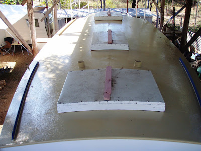
A 1" pipe is fitted to the cabin top ends to round off the deck join in higher wear areas. The 3mm thick steel cabin is tempoarily painted with machinery enamel for the build which controls oxidisation and makes for a cleaner work area.


The stern is moderately full with a moderate overhang, this gives ample bouyancy and storage aft. 
2 simple transom scuppers drain the cockpit directly overboard.

The opening transom porthole is an interesting development. Old sailing ships have had these for centuries but you dont see many on yachts. I met a wylo skipper who was quite happy with his transom porthole. Of the closing type, it could be left open  in nearly all conditions while on a swinging  anchor or mooring (rain, stong winds etc) and even while sailing in certain conditions. It helps ventilate the aft quarter berth area and can be larger than usual, say 7"-8" diameter.  I didn't opt for a second transom porthole on the  port side because the dry exhaust system normally  exits just below deck level to port (where it can be bunged shut for sea by reaching over from the cockpit.)

The double chine hull is formed by 2" flat bars welded on flat. This softens the chines and gives an almost roundbilge appearance. It's a bit harder to build than more conventional chine methods (flat bar on edge and round bar). I managed to get the 3mm hull plates above the lower chine to bow outwards a bit.

The keel base is about 20ft long and made of robust 1/2" (12mm) plate and allows wylos to be beached safely upright with the help of 2 grounding legs which bolt on amidships. Keel sides and bulkheads are 5mm plate. The hull bottom plate is 5mm. So theres more plate weight below the waterline where it's needed for stability and grounding strength. The internal ballast box is at the forward end of the keel. For ballast, I used scrap excavator track-pins and steel punchings from an engineering fabrication shop (in-exchange for some cartons of amber fluid) with a 5mm steel lid welded on top as per plans. 2 water tanks are aft of the ballast box.
I stuck with the ballast type design specifications, not only for costs sake but also by using a more dense material like lead, the centre of gravity would be lowered making the boat stiffer (ie snaps back from a roll faster, which would make it less comfortable) Lead would also lower the ballast box top by about half, this gives the chance to pack in extra weight such as jerry cans full of water fuel etc in there. This could then make the overall displacement heavier than first designed.
A 3mm plate streamlined "keel cooler" is welded on in the garboards, between the hull bottom and keel sides (one side visible in pic above, tapering end of keel cooler in pic below).  The principle of a keel-cooling system is roughly analagous to a cars radiator. It's an external heat-exchanger for the engine. Engine heat is dissipated to the outside and cooler water returns to the engine. The system is often used by heavy duty workboats such as prawn trawlers and marine engineering firms are usually familiar with it. More later.


Most external fittings are fabricated from mild steel. The sturdy rudder is a good example.  It's transom hung is as far back on the hull as possible to provide better steering control. Three gudgeons and pintles pairs mean that it wont fall off in a hurry. One pair is at deck level the second below the waterline and third set is near the keel base level. It has a sturdy 4" diameter pipe stock above the load waterline and a 2" diameter leading edge pipe below the waterline. The rudder blade is hollow and tapers aft to a 6mm trailing edge for better streamlining.  The top of the blade forms a natural step just above the waterline, which can be used by a fit person to re-board the yacht in an emergency, the rudder pipes, railings above are handholds. I saw a small ladder rung about 40cm above the waterline on one wylo, had a go fitting one but its trickier to get aligned right than  first imagined..

The trailing edge trim-tab is the wet end of a wind-powered self-steering system. It has 3 pipe gudgeons welded on so it can't part with the rudder.  The rudder and trim-tab assembly weighs a bit, so mechanical purchase is used to lift it off the 3 gudgeons. Once down it can be moved by one or two people. 


Work has recommenced on deck with the addition of some tempoary safety rails to keep everyone on deck. Its about 9ft from deck to the ground below.

The corrugated iron shed roof is about 7ft 6'' above the main deck and keeps the tropical sun and rains off but still allows a good breeze through. Indeed it is the coolest place to be in the tropics as breeze increases with height, a fact not missed by the designers of  highset houses.


The pipe bending frame (above) was re-discovered, modified slightly and used to bend the 25mm (middle) and 32mm (top) diameter quarter deck hand railings. It has am ordinary hydraulic car jack laid horrizontally in the steel frame.   The pipe is clamped into the holder. (I also used the fork of a  dark tree, seen in the background, for bends near the ends of the pipe). 

When doing the tempoary fitting up-clamping for any job, frequent use of "boatbuilders eye", to see if the curve looks right in relation to the hull, bulwarks etc from close up and further away is required.  Also to check if it is parallel to rails on the opposite side.  The side rails are parallel to the shear line of the gunwale, they look better  and it keeps the rail at a constant height from the deck. I may have made my aft side-railings a little higher than usual, hope this works out ok.


Here is a closer view of the pipe bending frame. The wooden wedge lifts the jack into alignment with the pipe to be bent.  I marked the rail every foot or so with engineers chalk on bending spots, the jack is pumped until the pipe bends a little (hard to reverse an overbend) then the jack released, the pipe springs back a bit, is taken out and checked for curve on the rail position..the process is repeated, checked in rail position, repeat. I also did some bends between the chalk marks. each bend is very slight but they all add up to make a fair curve. (A flexible wooden batten gives the best curve check)

Once everythings welded on, (cleats, eyelets etc) these rails are to be cut off  for hot dip galvanising. So at this fit up stage they need to have 10mm holes drilled into blind ends of pipework before welding pipes together so the galvanising plant will accept them. Hot dip galvavnising has fairly good resistance to wear and salt spray.

Alternatively,   pre-galvanised water pipes are used for all the railwork. Welds are power wire-brushed and zinc primed on completion of the days work.

An alternative pipe bending system which i also trialed (after building the hydraulic bender), has  2 T-pipes as seen below (from Alan Lucas' "The tools and materials of boatbuilding").


The pipe benders have 8-10" long T pipes welded onto 7-8ft long lever handles .
To bend the 2" bow railing, i made a beefed up T-pipe bender..it managed the gentle curves

but the tight curves on 2" pipe was too much. So fortunately knew a boatbuilding boilermaker friend and he suggested i try his pipe bending dye set for this.. cant remember too much but these were steel saddle shaped things with parabolic curves, they came in a set each for diferent pipe diameters. The dye fit into my steel hydraulic jack frame, pipes are supposed to be filled with sand, the side walls of the dye (plus sand) prevented the pipe from being flattened.


Another way, approach a local engineering firm to put  the tighter end bends in (These are later joined at the apex of the A-frame).