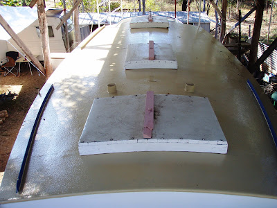
Up forward theres alot of flush deck space. The bulwarks have rounded 3/4" water pipe tops and the deck toe rails are 2" flat bar. The deck is 3mm steel plate. Photo below shows red oxide construction primer.
The hull was built on a North-South axis. I read or heard somewhere that the earths magnetic field gets set into the hull during welding and N-S build orientation would later make the compass anti-deviation easier to set up later.
I made tempoary construction hatches from old house hardwood and sheet metal which keeps it dry inside.
A 1" pipe is fitted to the cabin top ends to round off the deck join in higher wear areas. The 3mm thick steel cabin is tempoarily painted with machinery enamel for the build which controls oxidisation and makes for a cleaner work area.
The stern is moderately full with a moderate overhang, this gives ample bouyancy and storage aft.
2 simple transom scuppers drain the cockpit directly overboard.
The opening transom porthole is an interesting development. Old sailing ships have had these for centuries but you dont see many on yachts. I met a wylo skipper who was quite happy with his transom porthole. Of the closing type, it could be left open in nearly all conditions while on a swinging anchor or mooring (rain, stong winds etc) and even while sailing in certain conditions. It helps ventilate the aft quarter berth area and can be larger than usual, say 7"-8" diameter. I didn't opt for a second transom porthole on the port side because the dry exhaust system normally exits just below deck level to port (where it can be bunged shut for sea by reaching over from the cockpit.)
The double chine hull is formed by 2" flat bars welded on flat. This softens the chines and gives an almost roundbilge appearance. It's a bit harder to build than more conventional chine methods (flat bar on edge and round bar). I managed to get the 3mm hull plates above the lower chine to bow outwards a bit.
The keel base is about 20ft long and made of robust 1/2" (12mm) plate and allows wylos to be beached safely upright with the help of 2 grounding legs which bolt on amidships. Keel sides and bulkheads are 5mm plate. The hull bottom plate is 5mm. So theres more plate weight below the waterline where it's needed for stability and grounding strength. The internal ballast box is at the forward end of the keel. For ballast, I used scrap excavator track-pins and steel punchings from an engineering fabrication shop (in-exchange for some cartons of amber fluid) with a 5mm steel lid welded on top as per plans. 2 water tanks are aft of the ballast box.
I stuck with the ballast type design specifications, not only for costs sake but also by using a more dense material like lead, the centre of gravity would be lowered making the boat stiffer (ie snaps back from a roll faster, which would make it less comfortable) Lead would also lower the ballast box top by about half, this gives the chance to pack in extra weight such as jerry cans full of water fuel etc in there. This could then make the overall displacement heavier than first designed.
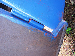
A 3mm plate streamlined "keel cooler" is welded on in the garboards, between the hull bottom and keel sides (one side visible in pic above, tapering end of keel cooler in pic below). The principle of a keel-cooling system is roughly analagous to a cars radiator. It's an external heat-exchanger for the engine. Engine heat is dissipated to the outside and cooler water returns to the engine. The system is often used by heavy duty workboats such as prawn trawlers and marine engineering firms are usually familiar with it. More later.
Most external fittings are fabricated from mild steel. The sturdy rudder is a good example. It's transom hung is as far back on the hull as possible to provide better steering control. Three gudgeons and pintles pairs mean that it wont fall off in a hurry. One pair is at deck level the second below the waterline and third set is near the keel base level. It has a sturdy 4" diameter pipe stock above the load waterline and a 2" diameter leading edge pipe below the waterline. The rudder blade is hollow and tapers aft to a 6mm trailing edge for better streamlining. The top of the blade forms a natural step just above the waterline, which can be used by a fit person to re-board the yacht in an emergency, the rudder pipes, railings above are handholds. I saw a small ladder rung about 40cm above the waterline on one wylo, had a go fitting one but its trickier to get aligned right than first imagined..
The trailing edge trim-tab is the wet end of a wind-powered self-steering system. It has 3 pipe gudgeons welded on so it can't part with the rudder. The rudder and trim-tab assembly weighs a bit, so mechanical purchase is used to lift it off the 3 gudgeons. Once down it can be moved by one or two people.

Work has recommenced on deck with the addition of some tempoary safety rails to keep everyone on deck. Its about 9ft from deck to the ground below.
The corrugated iron shed roof is about 7ft 6'' above the main deck and keeps the tropical sun and rains off but still allows a good breeze through. Indeed it is the coolest place to be in the tropics as breeze increases with height, a fact not missed by the designers of highset houses.
The pipe bending frame (above) was re-discovered, modified slightly and used to bend the 25mm (middle) and 32mm (top) diameter quarter deck hand railings. It has am ordinary hydraulic car jack laid horrizontally in the steel frame. The pipe is clamped into the holder. (I also used the fork of a dark tree, seen in the background, for bends near the ends of the pipe).
When doing the tempoary fitting up-clamping for any job, frequent use of "boatbuilders eye", to see if the curve looks right in relation to the hull, bulwarks etc from close up and further away is required. Also to check if it is parallel to rails on the opposite side. The side rails are parallel to the shear line of the gunwale, they look better and it keeps the rail at a constant height from the deck. I may have made my aft side-railings a little higher than usual, hope this works out ok.

Here is a closer view of the pipe bending frame. The wooden wedge lifts the jack into alignment with the pipe to be bent. I marked the rail every foot or so with engineers chalk on bending spots, the jack is pumped until the pipe bends a little (hard to reverse an overbend) then the jack released, the pipe springs back a bit, is taken out and checked for curve on the rail position..the process is repeated, checked in rail position, repeat. I also did some bends between the chalk marks. each bend is very slight but they all add up to make a fair curve. (A flexible wooden batten gives the best curve check)
Once everythings welded on, (cleats, eyelets etc) these rails are to be cut off for hot dip galvanising. So at this fit up stage they need to have 10mm holes drilled into blind ends of pipework before welding pipes together so the galvanising plant will accept them. Hot dip galvavnising has fairly good resistance to wear and salt spray.
Alternatively, pre-galvanised water pipes are used for all the railwork. Welds are power wire-brushed and zinc primed on completion of the days work.
An alternative pipe bending system which i also trialed (after building the hydraulic bender), has 2 T-pipes as seen below (from Alan Lucas' "The tools and materials of boatbuilding").
The pipe benders have 8-10" long T pipes welded onto 7-8ft long lever handles .
To bend the 2" bow railing, i made a beefed up T-pipe bender..it managed the gentle curves
but the tight curves on 2" pipe was too much. So fortunately knew a boatbuilding boilermaker friend and he suggested i try his pipe bending dye set for this.. cant remember too much but these were steel saddle shaped things with parabolic curves, they came in a set each for diferent pipe diameters. The dye fit into my steel hydraulic jack frame, pipes are supposed to be filled with sand, the side walls of the dye (plus sand) prevented the pipe from being flattened.
Another way, approach a local engineering firm to put the tighter end bends in (These are later joined at the apex of the A-frame).


