This is going back a bit in time, in the days of film cameras, dark hair and only monofocal glasses..time may have taken its toll so the descriptions of how it happened may need a bit of recall and editing later on. Idealy you would start with full project funding, a large shed ready for the hull, the location has to be where noise won't disturb residents either in an industrial zone (ideal) or in the country (not too far from industrial zone). The climates important - below about 27 deg C, above this and the heats too much when wearing overalls for welding. Easier to see this in retrospect, of course overall i did none of the above ideal things.
The process began with the plans, recommended book reading, a fair bit of study. I'm not a trady, have a science background, but have sailed and repaired a few small boats over the years. I'd never built any boat before, let alone a large steel one..maybe "the little men in big white coats (are coming to take you away, Ha- Ha"..on old song goes) should have been called in at this stage.! But they didnt come so i completed a TAFE welding course, part-time in the evenings. A few construction laboring jobs in the formative years also helped with the needed skill sets.
My wylo began underneath a high-set share rental house in a city of 110,000 souls. An old 1970 XY Falcon station wagon was the workhorse. A 4" angle grinder, 180amp arc welding gear and 2nd hand oxy acetylene cutting gear were bought along with mild steel stock - flat bar and a few sheets of 3mm. A straight edge, tape measure, engineers chalk, paint marker pens and large square were some other starting tools. I used 3.2mm welding rods on the 6mm thick flat bar. A welding/oxy cutting work bench was a good first project to practise my budding oxy-cutting and welding skills on.

Frame lofting
A sheet of 3mm steel used as a lofting surface (on a nice flat concrete floor) A steel scribe was used to mark the frames shape up on the steel sheet. First mark was the centerline, offset tables provided the measurements to mark out the chines and gunwales etc (frame corner points) on the sheet. A template of chines helped scribe the correct chine shapes then theses were connected by scribed lines to make the frame outline. The deck beam camber offset was marked and a flexible wooden batten used to mark a faired deck camber. The smallest frame - Frame 1 for the bow seemed like the logical one to do first.
2" x 1/4" flat bar segments were cut and fitted, joins to be welded were beveled to allow for complete penetration of weld. The first stage was to tack the pieces of the forefoot together. Carefull welding pattern (wish i could remember it) using short welds, then waiting for weld cooling shrinkage to see where the frame aligned on the lofted sheets scribe marks.When the frame was welded it was turned over, any slag from the first phase cut out with the grinder, then the other side welded. The small runs help reduce any distortion of the frame. Its pretty hard to rebend a flat bar on edge if its out, i used weld and quench method. A bead of weld is run down one side and is suddenly quenched with water..this pulls the steel the way you want it to go.

Frame 1 - ready for deck beam bending. The house mates black cat took great interest in the project.
Below is the frame bending device in the process of edge bending the deck beam. Later i discovered its better to cut the stringer notches prior to bending, so modified the bending frame to hold deck beams on edge and hit the stringer notch with a steel mallet, it bent easily at the stringer notch.

Corner gussets were welded in at the frame/deck beam join and at the lower join. This gives it greater strength. The welds were ground down afterwards.

Frame 1 completed!
well nearly, it was later laid back on the lofting platen and the hull center line angle iron tacked on (30x30mm section, for eventual frame set up)

One by one frames emerged from the basement, here is frame 5 (amidships)

The cabin end frames...with centre-line angle irons attached.

More frames come out to grace the exterior.

Black cat was always curious whenever something was going on. Limber (drainage) holes are cut into keel frames at this stage.
The stem and forefoot longitudinal frame is made of 40x10mm flat bar. Hitting floating logs or ice floes shouldnt be a problem, and might even survive a submerged sea container, but better take it easy around the marina.. (NB: The bender device in background has now gained vertical arms with slots for deck beam bending )

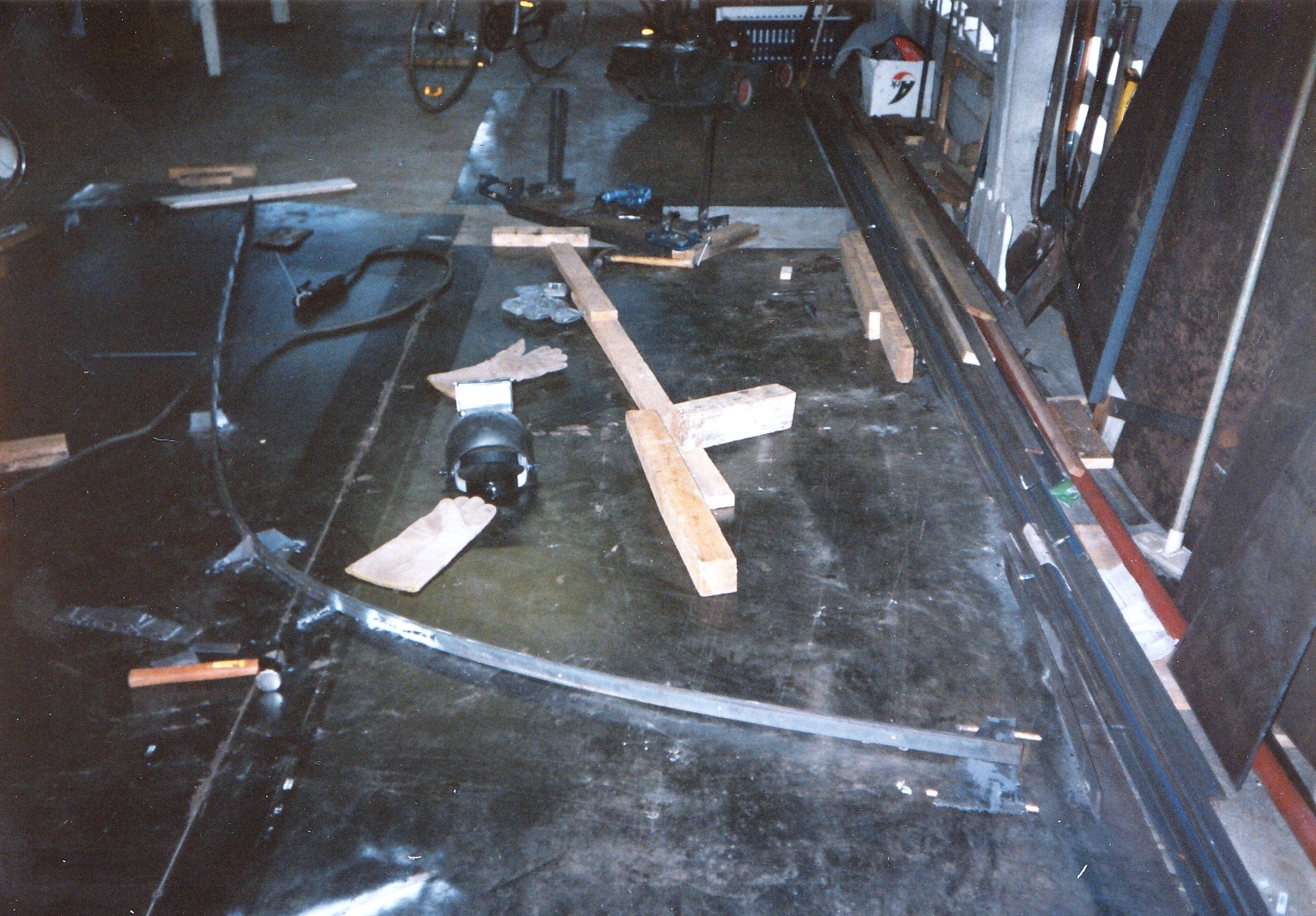
Eventually the day came when a highset suburban house on 700m2 was too small, so good friends helped load everything onto a hire trailer.

..and unloaded it at the big shed on a 25 acre block out of town. This was potentially a great wyloyard site..
Nice post. Being a desk jockey, with a little experience of general building/labouring in my youth, plus a bit of DIY, I'm very interested in the technical side of what you're doing - especially your bending jig. Did you gather this information from other Wylo builders? I think "The Mushroom Boat" is the most detailed Wylo build blog I've found.
ReplyDeleteGday Justin, Added a bit more on pipe bending methods (added to end of the first post for now). Also a labels cloud with "pipe bending methods",
ReplyDeleteMemory a bit hazy, but think I designed and built the deck frame bending jig myself.
ReplyDelete